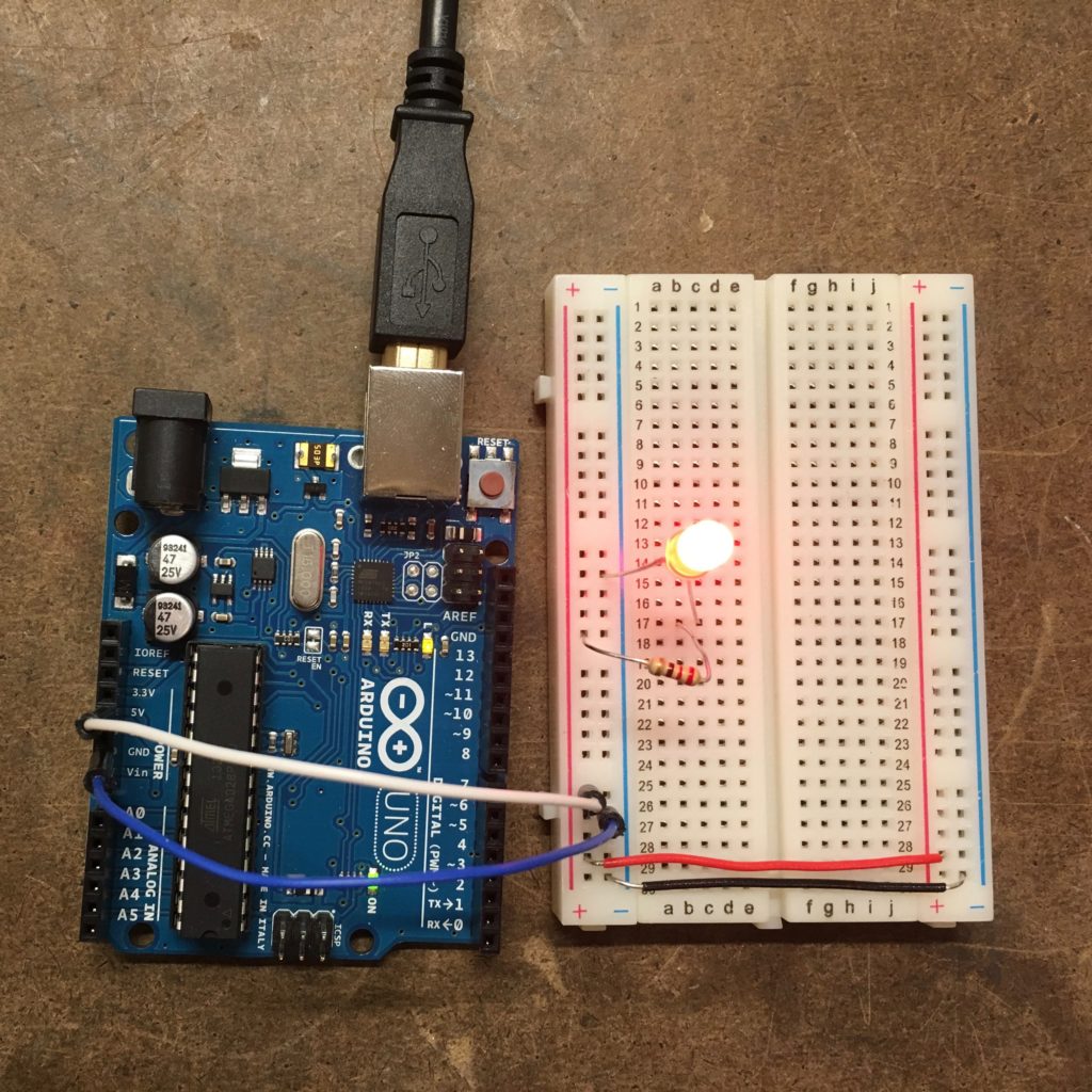
Having a single LED turn on was no problem: bring over power (5V) and ground from the Arduino, add a 220 Ω resistor, connect the LED to power and ground. Light!
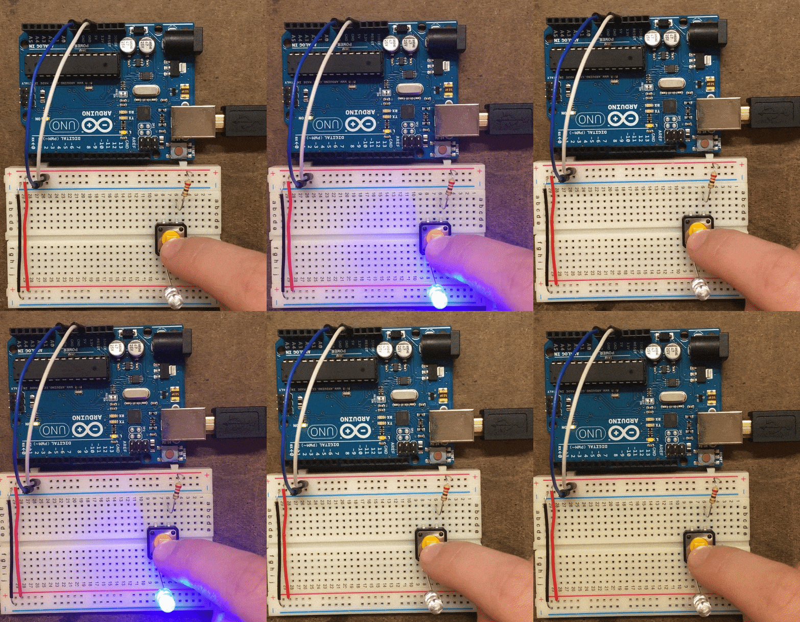
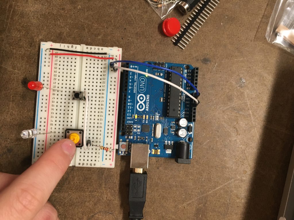
Adding a push button complicated the circuit. Initially I had wired in the circuit in such a way that the default state for the LED was on, and pushing the button turned it off. Originally I thought perhaps this was a property of the switch itself. Digging into the switch, I realized that I had placed the LED in the same row as where I had located the resistor. However, when I moved the LED to the other row of the switch, it worked as expected.
Wiring multiple switches in series and parallel was fairly straightforward once I understood how the electrons flowed through the push button. For demonstrating a series circuit, I wired the output of each switch to the input of the following switch.
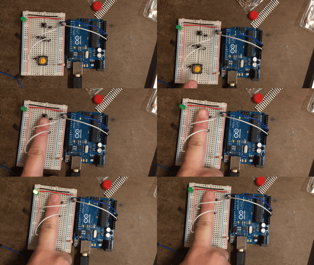
To complicate the series, I also added an LED at each switch, showing that the last LED (green) would only light up when the other red LEDs were also lit. Lesson learned: use a tripod when shooting video, one usable hand is not enough!
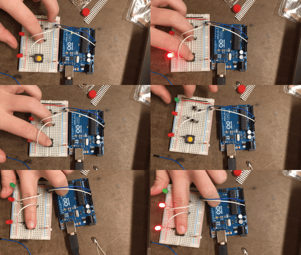
In parallel, I wired up an LED to each switch—whoops! I realized in hindsight that it was meant to be a single LED. However, the circuit still worked as expected. Had I just used one LED, I would have had to wire the output from each button to a new row that the LED was connected two—allowing either button to turn on the LED. Next time!
Part 2: making my own switch coming soon!